
AquaStudent
Members
Last year a bunch of my friends on youtube helped me win LEDGroupBuy's contest. The prize was $100 towards goodies over at the LEDGroupBuy's store.
I have been trying to put together a plan for the prize but everything didn't seem fitting. Finally, I decided to upgrade my 10g to a 29g and build the LED fixture for the 29. Here are the results.
Parts List:
1x 24" Extruded Aluminum Heatsink
2x 6 Pack of CREE XT-E "Cool White" LEDs (12 Total)
2x XT-E 60deg Optics
1x ArticAlumina Thermal Adhesive
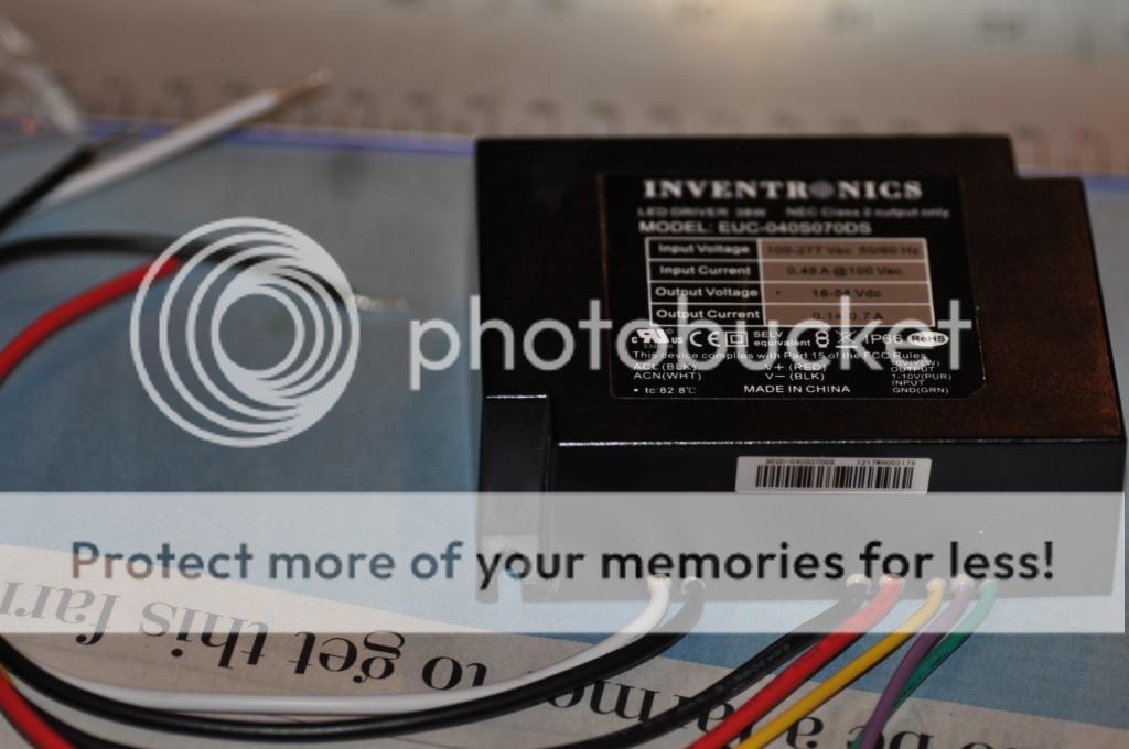
1x 40W Inventronics 750mA driver
1x 10,000K 1/2 Watt Potentiometer
 This image has been resized. Click this bar to view the full image.

Here is the build.
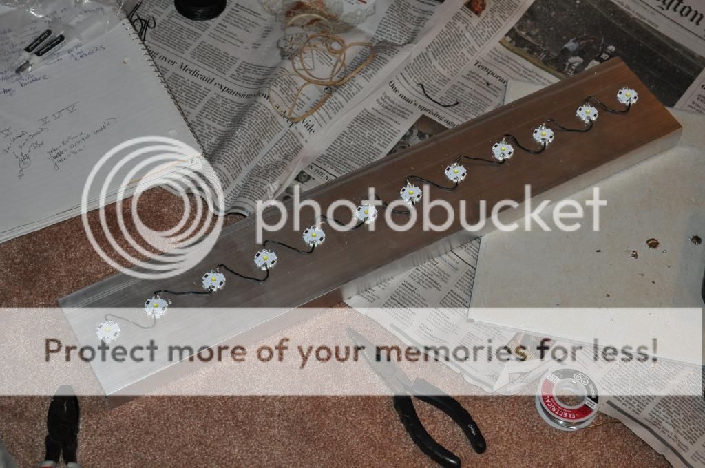
First I marked off 12 spots 2" apart from each other for the LED locations.
This image has been resized. Click this bar to view the full image.

Using Artic Alumina Thermal Adhesive (this stuff does not smell good) I plastered the LEDs in place. A rubber band works well as a clamp (although I'm not sure how necessary they actually were). The negative terminals on the LED were next to the positive terminals on the following LED.
This image has been resized. Click this bar to view the full image.

This image has been resized. Click this bar to view the full image.

Next I wired all of the LEDs in series. Positive to negative, positive to negative. I suck at soldering so this was quite a challenging process. I ended up getting frustrated with my soldering iron (which had a fairly corroded tip) and borrowed my neighbor's soldering gun. That worked so much better!
This image has been resized. Click this bar to view the full image.
This image has been resized. Click this bar to view the full image.

The next step was to wire in the potentiometer to the driver. That was simple enough, just solder the purple wire to the middle lead and the yellow and teal wires to the outside leads.
I wired the positive wires of the driver to the positive terminal on the first LED and the negative wire of the driver to the negative terminal. That completes the circuit. After wiring the plug into the driver it was good to go!
This image has been resized. Click this bar to view the full image.
Once I knew the circuit worked I siliconed in the Optics and the electric part of the build was done!
This image has been resized. Click this bar to view the full image.

I then built a canopy to hold the light. Simple 1x6 white wood goes together pretty easily with some finishing nails. A little paint later and we're good to go!
Primer
This image has been resized. Click this bar to view the full image.

Black Gloss
This image has been resized. Click this bar to view the full image.

Before (10 Gallon Tank, not much room to grow)
This image has been resized. Click this bar to view the full image.

After:
This image has been resized. Click this bar to view the full image.

This image has been resized. Click this bar to view the full image.

This image has been resized. Click this bar to view the full image.

I still need to drill a hole to mount the potentiometer out the back and use some black tape to hide some of the wires but other than that it's all finished.
Nice and simple

I have been trying to put together a plan for the prize but everything didn't seem fitting. Finally, I decided to upgrade my 10g to a 29g and build the LED fixture for the 29. Here are the results.
Parts List:
1x 24" Extruded Aluminum Heatsink
2x 6 Pack of CREE XT-E "Cool White" LEDs (12 Total)
2x XT-E 60deg Optics
1x ArticAlumina Thermal Adhesive
1x 40W Inventronics 750mA driver
1x 10,000K 1/2 Watt Potentiometer
 This image has been resized. Click this bar to view the full image.
Here is the build.
First I marked off 12 spots 2" apart from each other for the LED locations.
 This image has been resized. Click this bar to view the full image.
Using Artic Alumina Thermal Adhesive (this stuff does not smell good) I plastered the LEDs in place. A rubber band works well as a clamp (although I'm not sure how necessary they actually were). The negative terminals on the LED were next to the positive terminals on the following LED.
 This image has been resized. Click this bar to view the full image.
 This image has been resized. Click this bar to view the full image.
Next I wired all of the LEDs in series. Positive to negative, positive to negative. I suck at soldering so this was quite a challenging process. I ended up getting frustrated with my soldering iron (which had a fairly corroded tip) and borrowed my neighbor's soldering gun. That worked so much better!
 This image has been resized. Click this bar to view the full image.
 This image has been resized. Click this bar to view the full image.
The next step was to wire in the potentiometer to the driver. That was simple enough, just solder the purple wire to the middle lead and the yellow and teal wires to the outside leads.
I wired the positive wires of the driver to the positive terminal on the first LED and the negative wire of the driver to the negative terminal. That completes the circuit. After wiring the plug into the driver it was good to go!
 This image has been resized. Click this bar to view the full image.
Once I knew the circuit worked I siliconed in the Optics and the electric part of the build was done!
 This image has been resized. Click this bar to view the full image.
I then built a canopy to hold the light. Simple 1x6 white wood goes together pretty easily with some finishing nails. A little paint later and we're good to go!
Primer
 This image has been resized. Click this bar to view the full image.
Black Gloss
 This image has been resized. Click this bar to view the full image.
Before (10 Gallon Tank, not much room to grow)
 This image has been resized. Click this bar to view the full image.
After:
 This image has been resized. Click this bar to view the full image.
 This image has been resized. Click this bar to view the full image.
 This image has been resized. Click this bar to view the full image.
I still need to drill a hole to mount the potentiometer out the back and use some black tape to hide some of the wires but other than that it's all finished.
Nice and simple